| NO | Test Item | Test Condition | Requirements |
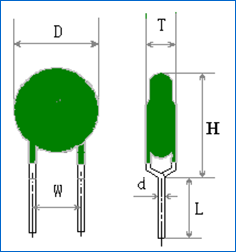
| 1 | Appearance Overall Dimension Rated zero power resistance | No visual damage,Pin no oxidation, no broken;Mark shall be complete, clear and identifiable. Measure by vernier caliper. Room Temperature:25±2℃;Place period:≥30min | Fig.1 Table 1 Table 2 |
| 2 | Switching Temperture | Curie temperature is corresponding value at 2 times of R25 R-T curve. | Table 2 |
| 3 | Withstand voltage | At 25±2℃ ambient environment,voltage 220V,last for 3S ;suddenly changed to 1000V, last 30S then cut off power . | 1000 Visual appearance no visible damage |
| 4 | Non-Operating Current | Place in 25±2℃ still air for 30min, power voltage:220VAC,applying with 30mA current,last 1h ,test its resistance change ratio(Test voltage between two PTC lead with voltmeter ,test PTC current with amperemeter ,then can get resistance of PTC). | 10mA(25±2℃) ┃ Resistance change rate ┃≤50% Inaction for 1 hour |
| 5 | Action Current | After placed in 25±2℃ still air for 30min , power voltage:220VAC,applying with 60Ma current, should go into high-impedance-state in 5 mins. | 30mA Action time ≤5min |
| 6 | Residual current | At 25±2℃ ambient environment,adjust voltage withstand tester to 1000V gradually , steady 10s get reading -current go through PTC,it is residual curent. | ≤2mA |
| 7 | Solderability | Use method of slotted weld ,stain with scaling powder , dip into 230±5℃ lead free tin(Sn96.5Ag3Cu0.5)molten solder groove along the axis direction, last for 3S~5S,body is 5mm far away with molten solder , take out and observe. | The terminals shall be uniformly tinned, and its area≥95% |
| 8 | Resistance to soldering Heat | Use method of slotted weld ,stain with scaling powder , dip into 260±5℃ lead free tin(Sn96.5Ag3Cu0.5)molten solder groove along the axis direction ,last for 3±1S,body is 2mm far away with molten solder,after place in room temperature for 24hours,check appearance and test zero power resistance then compare with initial resistance. | No visible mechanical damage. ┃Resistance change rate┃≤ 20% |
| 9 | High temperature discontinuous load | According to GB7153 1081th experiment,temp 60±2℃,voltage 265V,initial current 400mA,power on 90min,outage 30min,after total load 1000 hours , place in room temperature for 24hours,check appearance and test zero power resistance then compare with initial resistance. | No visible mechanical damage. ┃Resistance change rate┃≤ 30% |
| 10 | Strength of lead terminal | Do experiment according to GB2423-29 test U , test Ua, tension 10N and keep 10s ; test Ub , bend 90°,tension 5N,consecutive 2 times ;test Uc , turn around 180° ,consecutive 2 times ; Place in room temperature for 24 hours,test zero power resistance and compare with initial resistance. | ┃Resistance change rate┃≤ 20% |